

Ground Penetrating Radar (GPR) Overview
Ground Penetrating Radar (GPR) surveys can locate subsurface obstructions, including utilities (gas, water & sewer pipes), underground storage tanks (USTs), former swimming pools, underground vaults, water monitoring wells and buried debris.
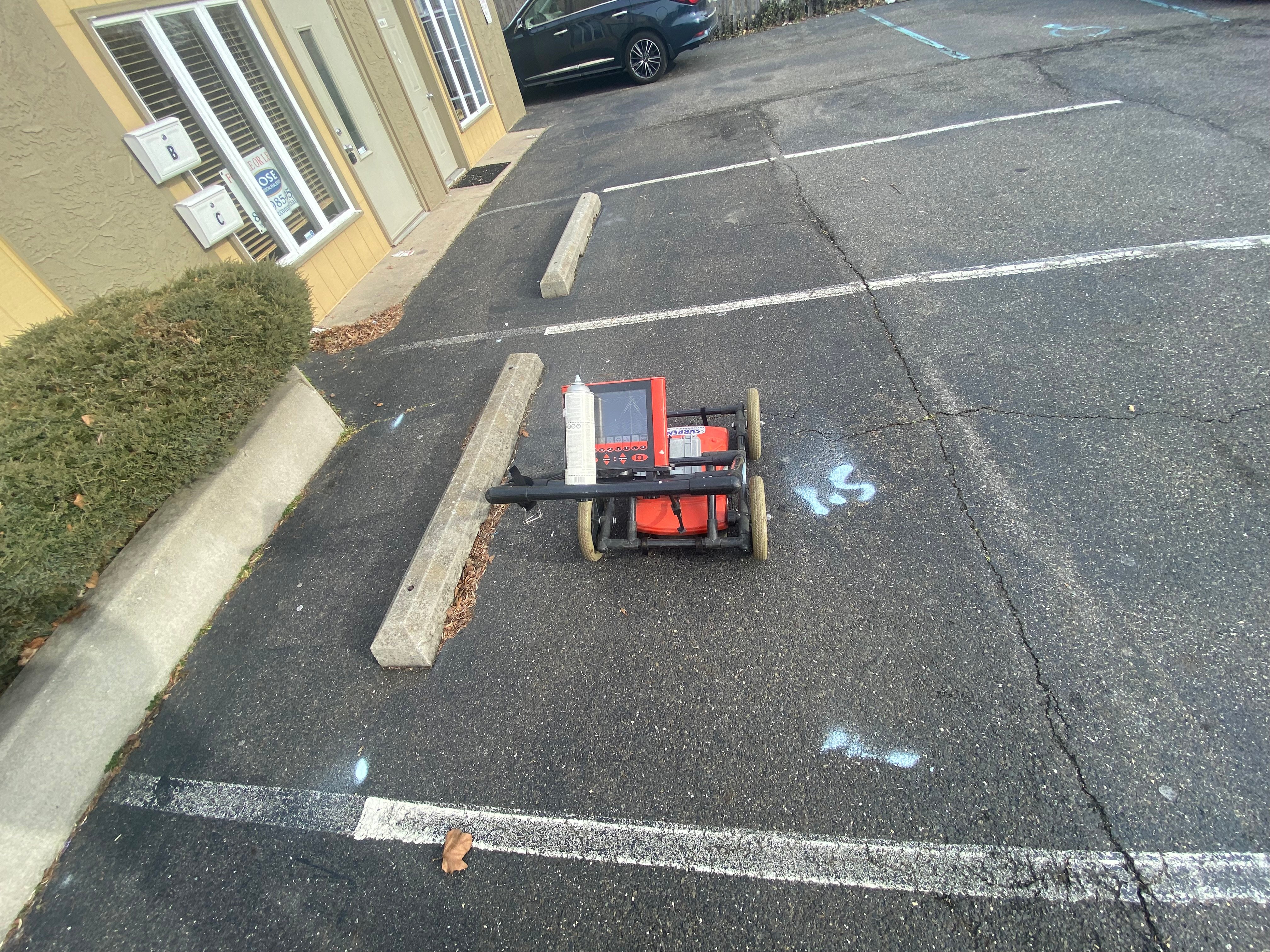
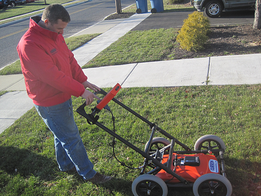
Curren’s GPR systems consist of a transceiver (the antenna), cables, and electronics package, a printer, and a power source. As the transceiver is pulled across the ground, a series of high frequency radio wave pulses are radiated downward into the subsurface. Some of the wave pulses are reflected back to the surface when they encounter a material having different electrical properties than the propagating media (like soil). An example of such a reflector would be a steel pipe buried in a sandy soil or a buried tank.
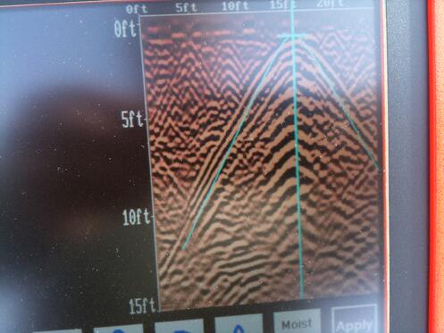
The above GPR signal indicates a buried steel tank.
Ground-penetrating radar is analogous to the seismic reflection technique, except that radar (microwaves) are utilized rather than acoustic waves. Radar waves generated at the surface are reflected from subsurface boundaries separating materials of contrasting conductivity and dielectric properties and are returned to the surface. Like seismic reflection, the greater the contrast, the greater the amplitude of the reflection. Data are displayed in time in a manner similar to seismic reflection data. The velocity at which the radar waves travel through a medium is related to the dielectric constant and knowledge of this parameter can allow conversion of time section to a depth section.
Radar waves are transmitted and received by a control unit operating a transducer antenna that is pulled along the ground. A time section is simultaneously displayed on a chart recorder, allowing the images to be examined during data acquisition. Adjustments in recording parameters can be made as necessary.
Effective depth of penetration ranges from about one foot in moist clay to 50 feet or more, in dry granular rocks and sediments, and is governed by ground electrical properties, as aforementioned. Also higher frequency signals are attenuated faster then lower frequencies. Several antennae are available so that wavelengths can be matched to target dimensions for optimum imaging. An example is this is that when you are performing concrete inspections, a different GPR antenna would be utilized than if you were looking for a buried tank.
In a GPR survey, high frequency (10 MHz to 3,000 MHz) electromagnetic (EM) pulses are used to detect changes in EM properties (dielectric permittivity, conductivity and magnetic permeability) as a function of depth.
The effective depth of GPR penetration is very site specific, occasionally varying 500% within 20 feet. Signal penetration decreases with increased soil conductivity. Conductive materials (e.g., clay) attenuate the GPR signal to the point that very little depth penetration is achieved. Penetration is greatest in unsaturated sands and fine gravels. Clayey, highly saline, and moist soils as well as areas covered by steel reinforced concrete and foundry slag allow for very little GPR penetration.
Optimum soils types for GPR penetration are gravels with minimal clay and silt content. Hard rock, ice, and fresh-water environs are also well suited to GPR
GPR Operation & Application
The GPR system is mounted on a wheeled carrier vehicle which is manually driven by the GPR operator. The GPR system transmits radar waves that are transmitted and received by a control unit operating a transducer / antenna that is pulled along the ground. A time section is simultaneously displayed on a chart recorder, allowing the images to be examined during data acquisition. Energy is propagated into the ground from a transmitting antenna and is reflected back to a receiving antenna from subsurface boundaries at which there are EM property contrasts. As the antennas are moved along the survey line, a series of scans are collected and positioned side by side to form a profile of the subsurface. Adjustments in recording parameters can be made as necessary.
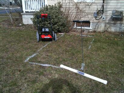
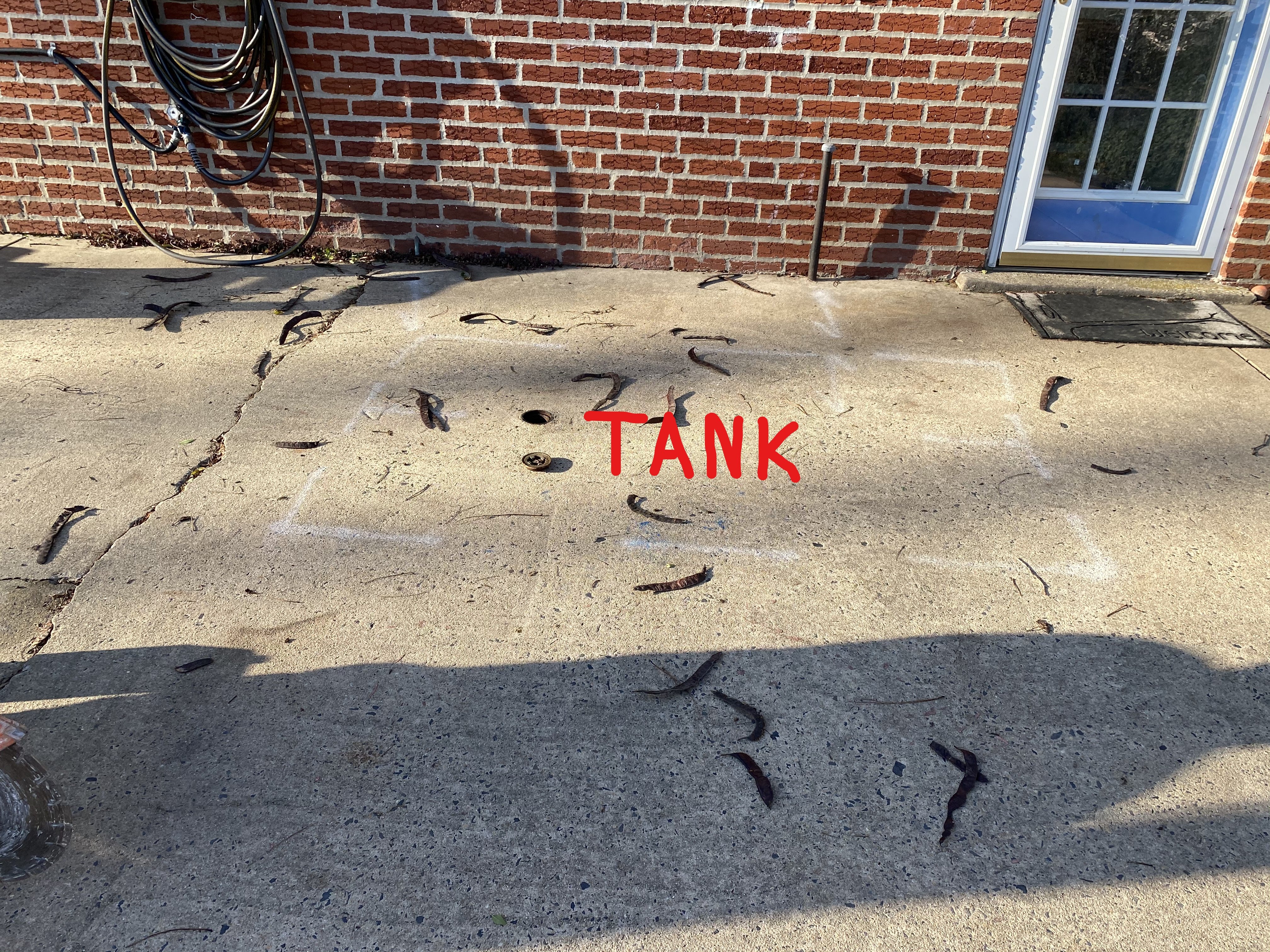
When the GPR unit has gone over an area that contains subsurface information, the GPR technician can record the information, stop and back up the cart, and the display cursor will show the position you're interested in on the screen. Then our Geophysical technician can accurately mark the ground at the exact position of the object with spray paint. Once the area has been marked the GPR survey can continue.
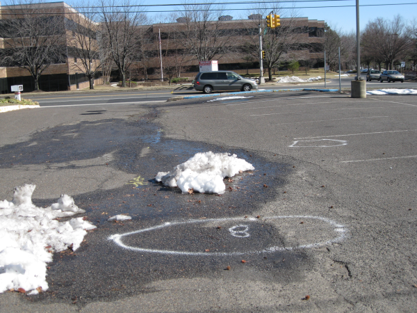
Areas in white are buried objects.
Higher frequency, shielded antennae can be used for tank/pipe locates. The penetration depth of the instrument is dependent on the chosen base frequency. The higher the frequency, the less the penetration. The trade-off is that the lower frequencies lose target resolution. Typically, 100 MHz to 50 MHz are used for bedrock detection, 500 MHz to 200 MHz antennae are used for tank locates, and 1000 MHz is used for rebar checking.
GPR can also be used to detect contaminants, if the conditions are right. The reflection delay time is controlled by the dielectric properties of the material. The signal velocity (m/ns) is approximately equal to one third the value of the dielectric constant. Some contaminants have different dielectric properties compared to the host geology. For example, GPR signals travel at 0.01 m/ns through sea water compared to 0.06 m/ns through clean, saturated sand.
The lateral resolution of a GPR survey depends upon the spacing of the GPR profiles and the rate at which data is collected along the profile. The vertical resolution of the technique is a complex function of the amplitude and wavelength of the EM pulse, the propagation characteristics of the host material and the target, the complexity of the geology, noise from man made and natural sources, and the depth shape and size of the target. Typically, vertical resolution of a few centimeters can be obtained with high frequency antennas (1 GHz) at depths of less than one meter, while lower frequency antennas (10 MHz) may have a resolution of a meter or so at depths to over fifty meters. Penetration depths of 5,000 meters have been achieved under certain conditions such as polar ice or salt deposits.
A GPR system radiates short pulses of high-frequency EM energy into the ground from a transmitting antenna. This EM wave propagates into the ground at a velocity that is related to the electrical properties of subsurface materials (specifically, the materials relative dielectric permittivity). When this wave encounters the interface of two materials having different dielectric properties (i.e., soil and water), a portion of the energy is reflected back to the surface, where it is detected by a receiver antenna and transmitted to a control unit for processing and display.
Depth penetration is a function of antenna frequency and the electrical conductivity of the soils in the survey area. Lower frequency antennas achieve greater depth penetration than higher frequency antennas, but have poorer spatial resolution. Conductive soils, such as clays, attenuate the radar waves much more rapidly than resistive soils such as dry sand and resistive rock.
The GPR method is limited to areas which do not contain high conductivity soils, or sediments which are saturated with salt water or other highly conductive fluids.
GPR Uses & Applications
-
Locate and delineate underground storage tanks (metallic and nonmetallic
-
Locate metallic and nonmetallic pipes and utility cables
-
Delineate pits and trenches containing metallic and nonmetallic debris
-
Delineate previously excavated and backfilled areas.
-
Map steel rebar in concrete and underground structures.
-
Map subsurface voids and cavities.
-
Define depth, orientation and location of underground utilities.
-
Find subsurface obstacles such as rocks and old foundations.
-
Locate lost monitoring wells.
-
Investigate boring sites.
-
Ordnance detection.
-
Locate Underground Storage Tanks (USTs).
Call the experts 888-301-1050